Tensile Test
BS EN ISO 6892-1 – Tensile testing of metallic materials Method of test at ambient temperature
Purpose of test
A tensile test applies stress in the opposite direction to a test which applies compressive stress, i.e. a tensile test puts the test item in tension and attempts to pull it apart. A tensile test can be used to assess the following:
-
The yield point of the specimen – the point at which the specimen undergoes plastic deformation;
-
The Ultimate Tensile Strength (UTS) of the specimen – the maximum load a specimen can withstand;
-
The ductility of the specimen – expressed as % elongation. There are different types of tensile tests for welds; these include:
-
The Transverse Tensile Test – used on joints containing butt welds; this will determine the tensile strength of a welded joint.
-
The All-Weld Tensile Test – used to test either the filler material properties, or the quality of the deposited weld metal as a whole;
-
The Cruciform Test – used to test the relative tensile strength of fillet weld joints between plates.
Stress-strain relationship
The relationship between stress and strain can be plotted on a graph to produce a stress-strain curve. The following example shows a curve for a low carbon steel.
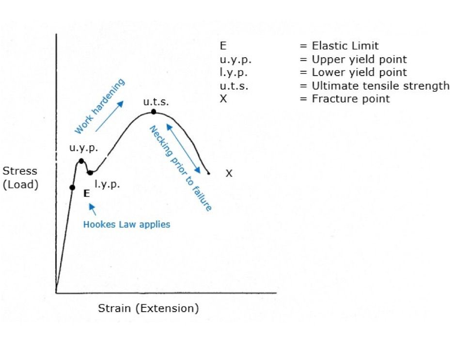
Elastic Limit E – also known as Youngs Modulus.
Strain (extension) is the result of stress (load applied), therefore as the load is applied the test piece will begin to extend. At first it will obey Hookes Law. Hookes Law shows that in the elastic range of the material, strain is proportional to stress. The elongation of the bar is directly proportional to the tensile strength and inversely proportional to the cross-sectional area.
If the load is removed at any point up to the Elastic Limit (E), the specimen will behave elastically and return to its original length. Beyond the elastic limit, the Upper Yield Point (UYP) is reached, this is where the material yields and plastic deformation occurs. At this point there is a noticeable drop in the applied load until the Lower Yield Point (LYP) is reached. Beyond the lower yield point, the load begins to increase again.
Yielding is the slipping of the atomic structure; it commences at the upper yield point and stops at the lower yield point. Yielding stops because the slipping action cold works the steel and increases the tensile strength.
After yielding, the load increases to the point of Ultimate Tensile Strength (UTS), this is the maximum load the specimen can withstand, it is not the point of fracture. Beyond the UTS, the specimen necks locally; this leaves a high load acting on the reduced cross-sectional area, therefore fracture at X rapidly follows.
Preparation of specimen
Test specimens are cut from designated areas of the welded assembly. The length and width, method of cutting (thermal or machine), and requirements for the removal or leaving of the weld reinforcement would be stated in the appropriate specification. The edges should be made smooth – normally filed – and any corners in the test area radiused slightly to reduce stress raisers.
On an All-Weld Tensile Test, it is a common requirement to test for the elongation percentage. In this case, two punch marks would be applied in line with the applied stress. The distance between the punch marks, which would be specified, is called the gauge length.
Test procedure
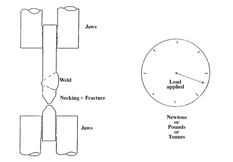
Two sets of vice jaws are used to clamp the test specimen at the top and bottom; hydraulic power is then applied to force the specimen apart. A dial, usually calibrated in pounds, tonnes or newtons, records the load applied. As the load increases, the dial registers the amount until fracture occurs.
For transverse tensile test made on C or C-Mn steel welds, fracture usually occurs in the parent material. A specimen which snaps in the weld region is usually acceptable providing the specification requirements are met.
In all cases, necking of the steel specimen prior to fracture should occur; the reduction in cross-sectional area indicates a ductile fracture. Steel specimens which snap and do not exhibit any necking are usually cause for rejection.
Calculations for ultimate tensile strength
The UTS can be calculated by dividing the maximum load applied by the least Cross-Sectional Area (CSA) of the test specimen. The maximum load applied is obtained from the dial on the machine; the least cross-sectional area is measured after testing with a micrometer.
Engineering stress is found by dividing the applied load by the original cross sectional area. True stress is the load divided by the actual cross sectional area.
Example 1
What is the UTS if a tensile test specimen had a least CSA of 1.015” x 0.627” and the maximum load applied was 46,000 lbs?
A.
B.
C.
Example 2
What is the UTS if a tensile test specimen had a least CSA of 1.015” x 0.627” and the maximum load applied was 46,000 lbs?
A.
B.
C.
D.
Calculations for elongation
The % elongation can be calculated by:
Example
A tensile test piece had an original gauge length of 50 mm; after testing this had increased to 62.5 mm. What is the percentage elongation?
A.
B.
C.
N = Newton One newton (1N) is defined as force F that accelerates an object with mass of one kilogram (1kg) one meter per second each second (1m/sec²).